Mil V-12 - The Flying Building
The Cold War threatened the world with nuclear annihilation. Amid escalating tensions, the Soviet Union faced an espionage nightmare that could cost them the atomic race. The Soviets needed a clandestine method to transport 25-ton nuclear intercontinental ballistic missiles across their sprawling landscapes without leaving the faintest trail for their American adversaries to find.
Their solution was nothing short of spectacular. Enter the Mil Mi-12, a colossal contraption with the size of an airliner fused with the versatility of an airlift helicopter.
When unveiled at the Paris Air Convention in 1971, it shocked the world; there had never been anything like it. The alarm bells rang in the US as strategists tried to unveil the purpose of such a staggering machine…
The Mil V-12 (NATO reporting name: Homer), given the project number Izdeliye 65 ("Item 65"), is a prototype helicopter designed in the Soviet Union and the largest helicopter ever built. The designation "Mi-12" would have been the designation for the production helicopter and did not apply to V-12 prototypes.
Design and Development
Design studies for a giant helicopter were started at the Mil OKB in 1959, receiving official sanction in 1961 by the GKAT (Gosudarstvenny Komitet po Aviatsionnoy Tekhnike - State Committee on Aircraft Technology) instructing Mil Moscow Helicopter Plant to develop a helicopter capable of lifting 20 to 25 tonnes (22 to 28 short tons). The GKAT directive was followed by a more detailed specification for the V-12 with hold dimensions similar to the Antonov An-22, intended to lift major items of combat material as well as 8K67, 8K75 and 8K82 inter-continental ballistic missiles (ICBM).
Design limitations forced Mil to adopt a twin rotor system but design studies of a tandem layout, similar to the Boeing CH-47 Chinook, revealed major problems. The single rotor layouts also studied, proved to be non-viable, leading to the transverse layout chosen for the finished article.
The transverse rotor system of the V-12, which eliminates the need for a tail rotor, consists of two Mil Mi-6 transmission systems complete with rotors mounted at the tips of the approximately 30 m (100 ft) span inverse tapered wings. Although the first use by Mil, the transverse system had been used by several of the early helicopters, including the Focke-Wulf Fw 61, Focke-Achgelis Fa 223 Drache and Kamov Ka-22 Vintokryl convertiplane.
Construction of the V-12 first prototype, after exhaustive testing with test-rigs and mock-ups including a complete transmission system, began at Panki in 1965. The airframe was largely conventional, using stressed skin construction methods with high strength parts machined from solid metal blocks. The large fuselage accommodated the 28.15 m × 4.4 m × 4.4 m (92 ft 4 in × 14 ft 5 in × 14 ft 5 in) cabin and crew section in the extreme nose, housing a pilot, co-pilot, flight engineer and electrical engineer in the lower cockpit, with the navigator and radio operator in the upper cockpit.
At the aft end of the fuselage access to the cabin is gained by large clamshell doors and a drop down cargo ramp with inbuilt retractable support jacks. Doors in the fuselage also give access to the cargo hold: two on the starboard side and three on the port side. Above the rear fuselage is a very large fin and rudder, with a moderately sized tailplane with dihedral fitted with end-plate fins (not fitted for the first flight).
The fixed undercarriage consists of large paired main-wheel units on oleo-pneumatic levered shock absorbers mounted at the junction of a strut system supporting the rotor systems and wings and connected to the centre fuselage by a tripod strut structure with the nose-leg attached aft of the crew section. A pair of bumper wheels are mounted at the rear of the fuselage keel and fixed support pads ensure that the cargo ramp is extended to the correct angle. Long braced struts also connected the transmission units to the rear fuselage forward of the fin. Cargo handling is done by means of a forklift or electric hoists on traveling beams.
The power system and wings are mounted above the centre fuselage with interconnecting shafts ensuring synchronisation of the main rotors which overlap by about 3 m (10 ft). Drag and lift losses are reduced by the inverse taper wings with minimum chord in regions of strongest down-wash. The interconnecting shafts also ensured symmetrical lift distribution in the event of an engine failure. To optimise control in roll and yaw the rotors are arranged to turn in opposite directions with the port rotor turning anti-clockwise and the starboard rotor turning clockwise, ensuring that the advancing blades pass over the fuselage.
Each power unit comprises two Soloviev D-25VF turbo-shaft engines mounted below the main gearboxes which each drive five-bladed 35 m (115 ft) diameter rotors and their synchronisation shafts which run from wing-tip to wing-tip. Each paired engine pod has large access panels which open up for maintenance access and also form platforms for servicing crews to operate from.
Control of the V-12 presented several problems to the designers and engineers due to the sheer size as well as the rotor layout. The pilot and co-pilot sat in the lower flight deck with a wide expanse of windows to give excellent visibility. Using conventional cyclic stick, collective lever and rudder pedals the pilots input their commands in a conventional fashion. Roll control is by differential collective pitch change on the left and right rotors, ensuring that sufficient lift is generated to prevent inadvertent sink. Yaw in the hover or low air speeds is achieved by tilting the rotor discs forward and backward differentially depending on direction of yaw required. At higher air speeds differential rotor control is gradually supplanted by the large aerodynamic rudder on the fin. Ascent and descent are controlled by the collective lever increasing or decreasing the pitch of both rotors simultaneously. Large elevators on the tailplane help control the fuselage attitude and provide reaction to pitching moments from the wing and variation on rotor disc angle.
The control system is complex due to the sheer size of the aircraft and the need to compensate for aeroelastic deformation of the structure, as well as the very large friction loads of the control rods, levers etc. To keep the control forces felt by the pilots to a minimum, the control system has three distinct stages. Stage one is the direct mechanical control from pilot input forces which are fed into a second stage, intermediate powered control system with low-powered hydraulic boosters transferring commands to stage three, the high-powered rapid action control actuators at the main gearboxes operating the swashplates directly.
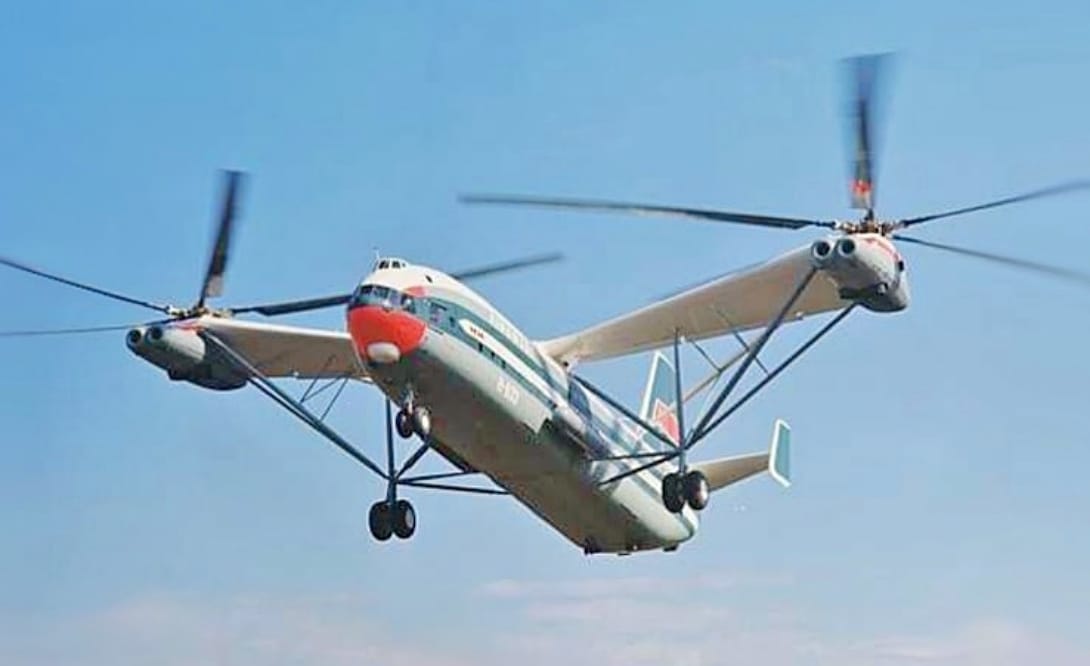
Top Photo: Mil V-12 prototype
Sources: YouTube; Wikipedia